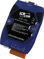
The GW-7553 PROFIBUS DP to Modbus TCP Gateway allows ProfiBus DP master devices to communicate with Modbus TCP protocol devices such as a sensor, PLC or the ET-7000 and I-8KEx-MTCP series. It also supports Modbus ASCII / RTU protocol for connection to other Modbus devices, such as the M-7000 series.
Configuration of the GW-7553 is simple, as the device has a built-in web server, which allows the module to be setup using a web browser.

|
Protocol & Hierarchy
|
DP-V0 & DP-V1 Slave
|
|
Supports PROFIBUS Transmission Rate (kbps)
|
9.6, 19.2, 45.45, 93.75, 187.5, 500, 1500, 3000, 6000, 12000
|
|
Transmission Rate Setting
|
detected automatically
|
|
Max Input Data Length
|
240 Bytes
|
|
Max Output Data Length
|
240 Bytes
|
|
Address Setting
|
0~126 set by DIP switch or EEPROM
|
|
Supports Modbus Mode
|
Master/Slave
|
|
Supports Modbus Format
|
RTU/ASCII/TCP
|
|
Ethernet
|
10/100 Base-TX
|
|
Supports COM 1 Baudrate (kbps)
|
2.4, 4.8, 9.6, 19.2, 38.4, 57.6, 115.2
|
|
Supports COM 1 Data Format
|
7/8 data bits, No/Odd/Even parity, 1/2 stop bit
|
|
Indicators
|
PWR, ERR, and RUN LEDs
|
|
Network Isolation Protection
|
2500 Vrms High Speed iCoupler
|
|
DC Isolation Protection
|
3000 VDC on PROFIBUS side
|
Web based configuration utility provides:
-
Provide safe value setting
-
Provide network configuration
-
Show diagnostic messages and device information
-
Show communication log between GW-7553 and Modbus devices
|
Hardware
|
|
CPU
|
80186, 80 MHz or compatible
|
|
SRAM/Flash/EEPROM
|
512 KB / 512 KB / 16 KB
|
|
Watchdog
|
Watchdog IC
CPU built-in
|
|
ESD Protection
|
4 kV class A
|
|
PROFIBUS Interface
|
|
Controller
|
Profichip VPC3+C
|
|
Transceiver
|
ADI ADM2486
|
|
Connector
|
9-pin female D-Sub
|
|
Baud Rate (bps)
|
9.6 k, 19.2 k, 45.45 k, 93.75 k, 187.5 k, 500 k, 1.5 M, 3 M, 6 M, 12 M
|
|
Transmission Distance (m)
|
Depend on baud rate (for example, max. 1200 m at 9.6 kbps )
|
|
Isolation
|
3000 VDC for DC-to-DC, 2500 Vrms for bus-to-logic
|
|
Protocol
|
DP-V0 & DP-V1
|
|
UART Interface
|
|
COM
|
RS-232 (For updating firmware and configuration)
|
|
COM Connector
|
5-pin screwed terminal block (TxD, RxD, RTS, CTS, GND )
|
|
Baud Rate (bps)
|
2400, 4800, 9600, 19200, 38400, 57600, 115200
|
|
Data bit
|
7, 8
|
|
Stop bit
|
1, 2
|
|
Parity
|
None, Even, Odd
|
|
Ethernet Interface
|
|
Controller
|
10/100Base-TX Ethernet Controller (Auto-negotiating, Auto_MDIX)
|
|
Connector
|
RJ-45 with LED indicator
|
|
LED
|
|
Round LED
|
PWR LED, RUN LED, ERR LED
|
|
Power
|
|
Power supply
|
Unregulated +10 ~ +30 VDC
|
|
Protection
|
Power reverse polarity protection, Over-voltage brown-out protection
|
|
Power Consumption
|
2.5 W
|
|
Mechanism
|
|
Installation
|
DIN-Rail
|
|
Dimensions
|
72mm x 33mm x 119mm (W x L x H)
|
|
Environment
|
|
Operating Temp.
|
-25 ~ 75 ?
|
|
Storage Temp.
|
-30 ~ 85?
|
|
Humidity
|
5 ~ 95% RH, non-condensing
|
Modbus Commands Supported
|
01
|
Read Coil Status
|
Read the ON/OFF status of discrete outputs in the slave
|
|
02
|
Read Input Status
|
Read the ON/OFF status of discrete inputs in the slave
|
|
03
|
Read Holding Registers
|
Read the binary contents of holding registers in the slave
|
|
04
|
Read Input Registers
|
Read the binary contents of input registers in the slave
|
|
05
|
Force Single Coil
|
Write a single output to either ON or OFF in the slave
|
|
06
|
Preset Single Register
|
Write an integer value into a single register in the slave
|
|
15
|
Force Multi. Coils
|
Write each coil in the sequence of coils to either ON or OFF in the slave
|
|
16
|
Preset Multi. Registers
|
Write a block of contiguous registers in the slave
|


