To give you the best experience we use cookies. Learn More

OK

100% Guarantee
View Cart (0)
0800 048 1057
0800 048 1057
Menu ▼

USB-2627 16-Bit, 1 MS/s, High-Speed DAQ Board With 16 SE Analog Inputs, 4 Analog Outputs

USB-2627 16-Bit, 1 MS/s, High-Speed DAQ Board with 16 SE Analog Inputs, 4 Analog Outputs
£1,19800

(£1,437.60 incl VAT)
FREE delivery to UK on orders over £500

100% Money Back
30 Day Guarantee

International Shipping
Over 100 Countries

Model:USB-2627

Description

The USB-2627 offers high-speed, multifunction data acquisition in a low-cost, board-only design. Each board offers voltage input, digital trigger input, counter input, timer output, digital I/O, and clock input. Analog output and clock output are also available.

Analog Input
Each USB-2627 board has a 16-bit, 1 MS/s ADC coupled with 16 SE analog inputs. The input range is fixed at ±10 V.

Trigger Input
The USB-2627 board has an external digital trigger input. The trigger mode is software-selectable for edge sensitive or level sensitive mode.


Edge sensitive mode is configurable for rising or falling edge.

Level sensitive mode is configurable for high or low level.


Analog Output
Four 16-bit, 1 MS/s analog output channels are built into the USB-2627 with a fixed output range of ±10 V. The maximum rate at which analog outputs can be updated depends on several factors, including the speed of the USB port.

Typically, with the A/D operating at the full 1 MS/s rate, each analog output updates continuously from computer memory at 1 MS/s regardless of the number of channels in a scan.

Digital I/O
Twenty-four TTL-level digital I/O lines are included in the USB-2627 board. Each channel is software-selectable for input or output. Each board typically provides a maximum transfer rate (system paced, asynchronous) of 4,000 8-bit port or single bit reads/writes per second.

Pull-Up/Pull-Down Configuration: Each USB-2627 board has a user-configurable jumper to configure the digital I/O for pull-up or pull-down (default).

Counter Input
Four 32-bit counters are included in USB-2627 devices. Each counter accepts frequency inputs up to 20 MHz.

Timer Output
The USB-2627 board has four pulse-width modulation (PWM) timer outputs. Each timer can generate a pulse output from 0.015 Hz to 32 MHz. Timer output frequency and other timer parameters are software-selectable.

External Clock I/O
The USB-2627 board provides one external clock input for pacing analog inputs, and one external clock input for pacing analog outputs.

Signal Connections
A 68-pin SCSI connector provides access to 16 SE analog inputs, up to four analog outputs, 24 digital I/O, four counters, and two timers.

Each board also includes four sets of header connectors that provide connection to the signals on the 68-pin connector as well as an additional 48 SE analog inputs (on the USB-2633 and USB-2637) and two additional timer outputs. Use these headers to connect to the C40FF-x ribbon cable or to custom, user-provided cables.

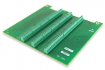
The optional TB-103 screw terminal board connects directly to the 40-pin headers on the back on each board, and secures to the board with the included stand-offs. The TB-103 provides access for up to 64 SE analog inputs (when using a USB-2633 or USB-2637), up to 4 analog outputs (when using a USB-2627 or USB-2637), 24 digital I/O and all counters/timers.

The optional TB-100 screw terminal board connects directly to the 68-pin SCSI connector using a CA-68-xx ribbon cable. The TB-100 provides access to 16 SE analog inputs, up to four analog outputs, 24 digital I/O, and all counters/timers.

When using the TB-100 with the USB-2633 or USB-2637, access the remaining 48 SE analog inputs through the 40-pin headers.


Features

  • Designed for OEM and embedded applications
  • Custom versions available for OEMs (contact factory)
  • 16-bit resolution
  • 1 MS/s sample rate
  • 16 single-ended analog inputs
  • Four 16-bit, 1 MS/s analog outputs
  • 24 digital I/O
  • Four 32-bit event counters
  • Four timer outputs
  • USB powered (no external power required)
  • Small, compact design (6" x 5.93")
  • View the complete USB-2600 Series


Software


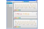
  • Support for DAQami, easy-to-use advanced data logging application to acquire,
  • view, and log data
  • TracerDAQ® software for acquiring and displaying data and generating analog signals
  • Universal Library includes support for Visual Studio® and Visual Studio® .NET, including examples for Visual C++®, Visual C#®, Visual Basic®, and Visual Basic® .NET
  • Universal Library for Android™ includes support and examples for the Android 3.1 platform (API level 12) and later
  • Example ready-to-run demo apps for Android are available on Google Play™
  • InstaCal software utility for installing, calibrating, and testing
  • ULx for NI LabVIEW™
  • Comprehensive drivers for DASYLab®
  • Supported Operating Systems: Windows® 8/7/Vista®/XP SP2, 32-bit or 64-bit; Linux®

Specifications

Product Specifications

Technical

Product Manual

Description

The USB-2627 offers high-speed, multifunction data acquisition in a low-cost, board-only design. Each board offers voltage input, digital trigger input, counter input, timer output, digital I/O, and clock input. Analog output and clock output are also available.

Analog Input
Each USB-2627 board has a 16-bit, 1 MS/s ADC coupled with 16 SE analog inputs. The input range is fixed at ±10 V.

Trigger Input
The USB-2627 board has an external digital trigger input. The trigger mode is software-selectable for edge sensitive or level sensitive mode.


Edge sensitive mode is configurable for rising or falling edge.

Level sensitive mode is configurable for high or low level.


Analog Output
Four 16-bit, 1 MS/s analog output channels are built into the USB-2627 with a fixed output range of ±10 V. The maximum rate at which analog outputs can be updated depends on several factors, including the speed of the USB port.

Typically, with the A/D operating at the full 1 MS/s rate, each analog output updates continuously from computer memory at 1 MS/s regardless of the number of channels in a scan.

Digital I/O
Twenty-four TTL-level digital I/O lines are included in the USB-2627 board. Each channel is software-selectable for input or output. Each board typically provides a maximum transfer rate (system paced, asynchronous) of 4,000 8-bit port or single bit reads/writes per second.

Pull-Up/Pull-Down Configuration: Each USB-2627 board has a user-configurable jumper to configure the digital I/O for pull-up or pull-down (default).

Counter Input
Four 32-bit counters are included in USB-2627 devices. Each counter accepts frequency inputs up to 20 MHz.

Timer Output
The USB-2627 board has four pulse-width modulation (PWM) timer outputs. Each timer can generate a pulse output from 0.015 Hz to 32 MHz. Timer output frequency and other timer parameters are software-selectable.

External Clock I/O
The USB-2627 board provides one external clock input for pacing analog inputs, and one external clock input for pacing analog outputs.

Signal Connections
A 68-pin SCSI connector provides access to 16 SE analog inputs, up to four analog outputs, 24 digital I/O, four counters, and two timers.

Each board also includes four sets of header connectors that provide connection to the signals on the 68-pin connector as well as an additional 48 SE analog inputs (on the USB-2633 and USB-2637) and two additional timer outputs. Use these headers to connect to the C40FF-x ribbon cable or to custom, user-provided cables.

The optional TB-103 screw terminal board connects directly to the 40-pin headers on the back on each board, and secures to the board with the included stand-offs. The TB-103 provides access for up to 64 SE analog inputs (when using a USB-2633 or USB-2637), up to 4 analog outputs (when using a USB-2627 or USB-2637), 24 digital I/O and all counters/timers.

The optional TB-100 screw terminal board connects directly to the 68-pin SCSI connector using a CA-68-xx ribbon cable. The TB-100 provides access to 16 SE analog inputs, up to four analog outputs, 24 digital I/O, and all counters/timers.

When using the TB-100 with the USB-2633 or USB-2637, access the remaining 48 SE analog inputs through the 40-pin headers.
 

Features


Software


Specifications

Product Specifications

Technical

Product Manual

Recently Viewed Products